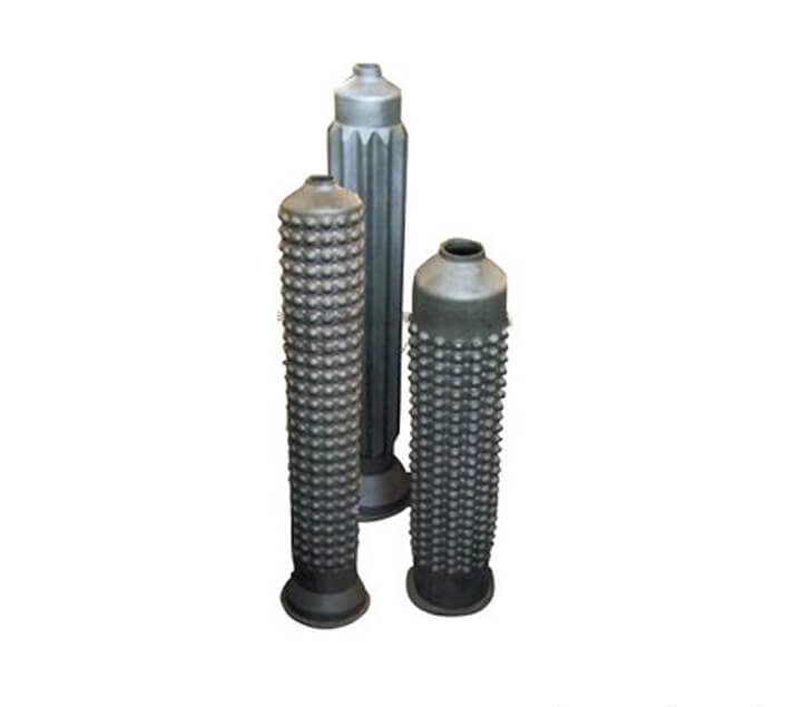
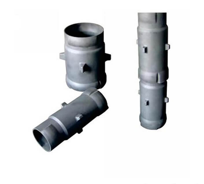
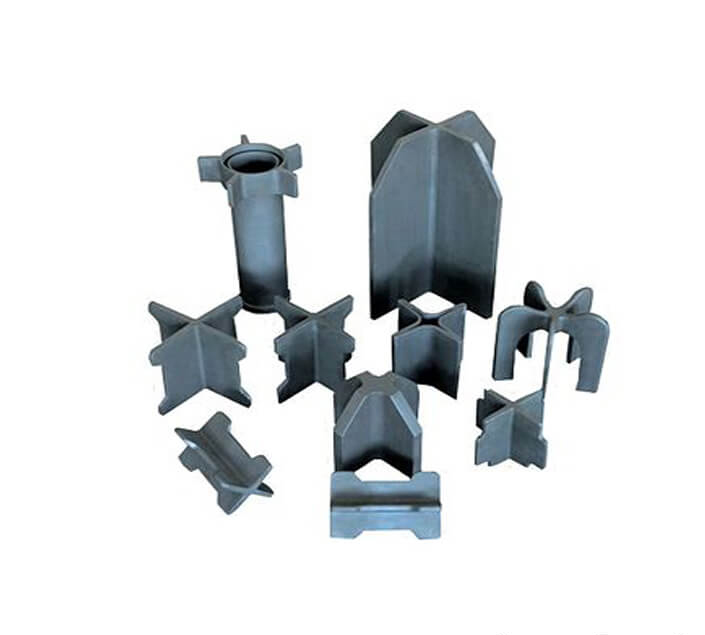
Introduction silicon carbide SIC Ceramic Radiant Tube Burner
Combustion air is fed into the air part of the burner via the combustion air pipe. It usually flows completely between the recuperator and the combustion pipe, during this the air is warmed by the hot off gases which flow back on the outside of the recuperator. The largest part of the warm combustion air flows through the incoming air bore holes into the inside of the combustion pipe and then through the twist plate into the combustion chamber. It is mixed here with the combustion gas, the smaller part of the combustion air the secondary air flows through the annular gap between the combustion pipe mouth and the recuperator, the mixture of the air with the outgoing flame gases leads to complete combustion, the sir plate divides the combustion air volume flow. One part may take the cooling air path inside the combustion pipe, depending on requirements the technical firing level of efficiency and the mission of nitrogen oxides can be influenced, the simultaneous cooling of the gas lance has benefits when operating the burner near its top temperature, the combustion gas flows via the connection pipe to the gas part and through the gas pipe to the twist plate, the largest part of the gas volume flow passes through the radial oriented openings into the combustion chamber and mixes with the combustion air.
Characteristics SIC Radiant Tube Burner
A small part close in to a separately located ignition chamber, it is ignited here by means of a high voltage ignition spark, the combustion spreads to the combustion chamber, immediate combustion stability is achieved, so that cold starts are also no problem. The hot flue gases flow back to the recuperator transfer their heat and leave the burner in a cooled off state, this warming of the air leads to a larger increase in the volume of the flame gases, this results in a high outgoing speed of more than 100 meters per second, this is the reason why these types of burner fall under the heading. High-speed burners via a limiting jet dosed scavenging air is fed to the combustion gas in the gas part, it flows even when the gas and combustion air volume flow has been shut down by the burner, when the burner is shut down the rest of the combustion gas is removed from the gas lamps to avoid an afterglow, in cooling mode the combustion gas is switched off an additional cold air is fed through the cooling air pipe to the burner for rapid cooling of the furnace space and/or jet pipes, this cold air flows into the inside of the combustion pipe to the combustion chamber which results in a higher cooling effect.
Technical Data Sheet of Radiant Tube Burner
| Item | Unit | Data |
| Max Working temperature | ℃ | 1380 |
| Density | g/cm³ | ≥3.02 |
| Porosity | % | <0.1% |
| Bending Strength | Mpa | 250(20℃) |
| Mpa | 280(1200℃) | |
| Modulus of elasticity | Gpa | 330(20℃) |
| Gpa | 300(1200℃) | |
| Thermal conductivity | W/m.k | 45(1200℃) |
| Coefficient of thermal expansion | K-1×10⁻⁶ | 4.5 |
| Rigidity | 13 | |
| Acid alkaline-proof | Excellent |
Related Products:
This post is also available in: Arabic French German Indonesian Italian Japanese Korean Portuguese (Portugal) Russian Spanish


